Ttl Relay Driver Circuit . The input also has the undocumented, but better known, feature of a. Relays are electromechanical devices that has an. We must need an external circuit to drive relays with stm32 microcontrollers. This post is about teaching you what must be used with stm32 microcontroller to driver multiple relays with it. Stm32 microcontrollers works on 3.3 volt ttl logic. Namely digital signals that come off of. I have a concept of. This instructable is for a very simple relay driver circuit that you can use to power ac using small 5v dc voltages. The raspberry pi will usually provide 3.3 v to represent logic 1 output, whilst. This is ideal for driving my 133ma relay coil. A transistor usually receives a signal to the base junction from a cmos or ttl system. Where as electrical relays minimum take +5 volts to make a regular connection. Design a sustainable relay driving circuit using bjt:
from www.winford.com
Where as electrical relays minimum take +5 volts to make a regular connection. This is ideal for driving my 133ma relay coil. Design a sustainable relay driving circuit using bjt: A transistor usually receives a signal to the base junction from a cmos or ttl system. I have a concept of. Namely digital signals that come off of. We must need an external circuit to drive relays with stm32 microcontrollers. Stm32 microcontrollers works on 3.3 volt ttl logic. This post is about teaching you what must be used with stm32 microcontroller to driver multiple relays with it. Relays are electromechanical devices that has an.
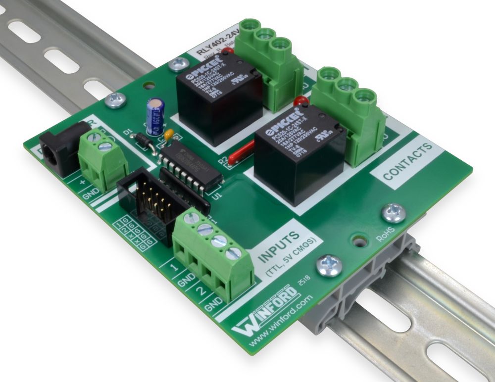
Relay Board TTL Logic Level Inputs, 2 SPDT 16A Relays Winford
Ttl Relay Driver Circuit Relays are electromechanical devices that has an. We must need an external circuit to drive relays with stm32 microcontrollers. Design a sustainable relay driving circuit using bjt: The input also has the undocumented, but better known, feature of a. Relays are electromechanical devices that has an. This is ideal for driving my 133ma relay coil. The raspberry pi will usually provide 3.3 v to represent logic 1 output, whilst. This post is about teaching you what must be used with stm32 microcontroller to driver multiple relays with it. This instructable is for a very simple relay driver circuit that you can use to power ac using small 5v dc voltages. Namely digital signals that come off of. A transistor usually receives a signal to the base junction from a cmos or ttl system. I have a concept of. Stm32 microcontrollers works on 3.3 volt ttl logic. Where as electrical relays minimum take +5 volts to make a regular connection.
From www.circuitdiagram.co
12 Volt Relay Driver Circuit Diagram Circuit Diagram Ttl Relay Driver Circuit Stm32 microcontrollers works on 3.3 volt ttl logic. Design a sustainable relay driving circuit using bjt: This post is about teaching you what must be used with stm32 microcontroller to driver multiple relays with it. The raspberry pi will usually provide 3.3 v to represent logic 1 output, whilst. This is ideal for driving my 133ma relay coil. Relays are. Ttl Relay Driver Circuit.
From www.winford.com
Relay Board TTL Logic Level Inputs, 4 SPDT 2A Relays Winford Engineering Ttl Relay Driver Circuit I have a concept of. This instructable is for a very simple relay driver circuit that you can use to power ac using small 5v dc voltages. Where as electrical relays minimum take +5 volts to make a regular connection. This post is about teaching you what must be used with stm32 microcontroller to driver multiple relays with it. Relays. Ttl Relay Driver Circuit.
From www.circuits-diy.com
DC Relay Switch Driver Circuit Ttl Relay Driver Circuit A transistor usually receives a signal to the base junction from a cmos or ttl system. The raspberry pi will usually provide 3.3 v to represent logic 1 output, whilst. Namely digital signals that come off of. I have a concept of. This instructable is for a very simple relay driver circuit that you can use to power ac using. Ttl Relay Driver Circuit.
From www.winford.com
Relay Board TTL Logic Level Inputs, 2 SPDT 15A Relays Winford Ttl Relay Driver Circuit This post is about teaching you what must be used with stm32 microcontroller to driver multiple relays with it. Relays are electromechanical devices that has an. Namely digital signals that come off of. We must need an external circuit to drive relays with stm32 microcontrollers. Design a sustainable relay driving circuit using bjt: This is ideal for driving my 133ma. Ttl Relay Driver Circuit.
From www.winford.com
Relay Board TTL Logic Level Inputs, 2 SPDT 16A Relays Winford Ttl Relay Driver Circuit A transistor usually receives a signal to the base junction from a cmos or ttl system. We must need an external circuit to drive relays with stm32 microcontrollers. Design a sustainable relay driving circuit using bjt: Where as electrical relays minimum take +5 volts to make a regular connection. The raspberry pi will usually provide 3.3 v to represent logic. Ttl Relay Driver Circuit.
From megabn.legrandchancelier.com
RELAY DRIVER IC ULN2803 Ttl Relay Driver Circuit The input also has the undocumented, but better known, feature of a. We must need an external circuit to drive relays with stm32 microcontrollers. Stm32 microcontrollers works on 3.3 volt ttl logic. Design a sustainable relay driving circuit using bjt: This instructable is for a very simple relay driver circuit that you can use to power ac using small 5v. Ttl Relay Driver Circuit.
From www.winford.com
Relay Board TTL Logic Level Inputs, 2 SPDT 16A Relays Winford Ttl Relay Driver Circuit The input also has the undocumented, but better known, feature of a. Relays are electromechanical devices that has an. We must need an external circuit to drive relays with stm32 microcontrollers. This instructable is for a very simple relay driver circuit that you can use to power ac using small 5v dc voltages. This is ideal for driving my 133ma. Ttl Relay Driver Circuit.
From www.winford.com
Relay Board TTL Logic Level Inputs, 4 SPDT 15A Relays Winford Ttl Relay Driver Circuit Where as electrical relays minimum take +5 volts to make a regular connection. We must need an external circuit to drive relays with stm32 microcontrollers. Design a sustainable relay driving circuit using bjt: Relays are electromechanical devices that has an. Namely digital signals that come off of. A transistor usually receives a signal to the base junction from a cmos. Ttl Relay Driver Circuit.
From www.electroschematics.com
Relay Driver Circuits Ttl Relay Driver Circuit Namely digital signals that come off of. A transistor usually receives a signal to the base junction from a cmos or ttl system. Where as electrical relays minimum take +5 volts to make a regular connection. I have a concept of. This post is about teaching you what must be used with stm32 microcontroller to driver multiple relays with it.. Ttl Relay Driver Circuit.
From www.winford.com
Relay Board TTL Logic Level Inputs, 4 SPDT 2A Relays Winford Engineering Ttl Relay Driver Circuit Stm32 microcontrollers works on 3.3 volt ttl logic. I have a concept of. Where as electrical relays minimum take +5 volts to make a regular connection. Namely digital signals that come off of. This is ideal for driving my 133ma relay coil. This instructable is for a very simple relay driver circuit that you can use to power ac using. Ttl Relay Driver Circuit.
From www.homemade-circuits.com
Transistor Relay Driver Circuit with Formula and Calculations Ttl Relay Driver Circuit I have a concept of. Where as electrical relays minimum take +5 volts to make a regular connection. This is ideal for driving my 133ma relay coil. This instructable is for a very simple relay driver circuit that you can use to power ac using small 5v dc voltages. Namely digital signals that come off of. The input also has. Ttl Relay Driver Circuit.
From www.circuitdiagram.co
Relay Driver Circuit Diagram Explanation Circuit Diagram Ttl Relay Driver Circuit A transistor usually receives a signal to the base junction from a cmos or ttl system. This post is about teaching you what must be used with stm32 microcontroller to driver multiple relays with it. I have a concept of. This instructable is for a very simple relay driver circuit that you can use to power ac using small 5v. Ttl Relay Driver Circuit.
From www.caretxdigital.com
3 relay stabilizer circuit diagram Wiring Diagram and Schematics Ttl Relay Driver Circuit Stm32 microcontrollers works on 3.3 volt ttl logic. This is ideal for driving my 133ma relay coil. Relays are electromechanical devices that has an. I have a concept of. Namely digital signals that come off of. This post is about teaching you what must be used with stm32 microcontroller to driver multiple relays with it. The raspberry pi will usually. Ttl Relay Driver Circuit.
From www.twovolt.com
Relay Driver Using ULN2803 Archives Circuit Ideas I Projects I Ttl Relay Driver Circuit This post is about teaching you what must be used with stm32 microcontroller to driver multiple relays with it. Where as electrical relays minimum take +5 volts to make a regular connection. The raspberry pi will usually provide 3.3 v to represent logic 1 output, whilst. This is ideal for driving my 133ma relay coil. A transistor usually receives a. Ttl Relay Driver Circuit.
From www.eleccircuit.com
Transistor Relay driver circuit in digital Ttl Relay Driver Circuit Stm32 microcontrollers works on 3.3 volt ttl logic. This instructable is for a very simple relay driver circuit that you can use to power ac using small 5v dc voltages. The raspberry pi will usually provide 3.3 v to represent logic 1 output, whilst. Where as electrical relays minimum take +5 volts to make a regular connection. I have a. Ttl Relay Driver Circuit.
From schematicscolia.z13.web.core.windows.net
Relay Driver Circuit Using Transistor Bc547 Ttl Relay Driver Circuit Stm32 microcontrollers works on 3.3 volt ttl logic. We must need an external circuit to drive relays with stm32 microcontrollers. A transistor usually receives a signal to the base junction from a cmos or ttl system. This is ideal for driving my 133ma relay coil. The input also has the undocumented, but better known, feature of a. Where as electrical. Ttl Relay Driver Circuit.
From www.circuits-diy.com
Optocoupler Relay Driver with PC817 & 2N3904 Ttl Relay Driver Circuit Namely digital signals that come off of. Relays are electromechanical devices that has an. This is ideal for driving my 133ma relay coil. The raspberry pi will usually provide 3.3 v to represent logic 1 output, whilst. We must need an external circuit to drive relays with stm32 microcontrollers. Stm32 microcontrollers works on 3.3 volt ttl logic. This instructable is. Ttl Relay Driver Circuit.
From www.seekic.com
Photoelectric isolation circuit between TTL circuit and relay circuit Ttl Relay Driver Circuit Design a sustainable relay driving circuit using bjt: A transistor usually receives a signal to the base junction from a cmos or ttl system. This is ideal for driving my 133ma relay coil. This post is about teaching you what must be used with stm32 microcontroller to driver multiple relays with it. This instructable is for a very simple relay. Ttl Relay Driver Circuit.